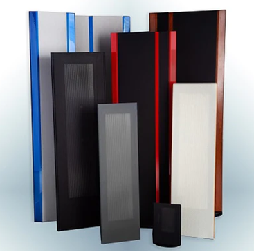
Magneplanar MMC 2 General Instruction Manual
Table of Contents
- Introduction/General Description
- Carton Contents
- Packaging
- Installation and Placement
- Phasing
- Speaker Angle Adjustment
- Bass Management and Processor Settings
- Tweeter Level Control
- Service and Shipping
- Specifications
You don't like to read manuals? We understand, but, please take the time to carefully read "Placement and Installation" and "Phasing".
If you are a do-it-yourselfer, the MMC 2 was designed with you in mind. See the Installation Manual for details.
-
Introduction / General Description
Congratulations on your purchase of the Magneplanar MMC 2. The MMC 2 is a 3-way, motorized, speaker designed for music or home theater applications. The MMC 2 boasts a "faster" midrange and a quasi-ribbon tweeter and quasi-ribbon super tweeter.
-
Carton Contents
- 1 - Pair of MMC 2 with Motorized Wall Mounts
- 1 - Long 5/64 inch allen wrench
- 4 each wall brackets
- 1 - Speaker Logo
- 1 - MMC 2 General Instruction Manual
- 1 - MMC 2 Installation Instruction Manual
- 1 - Each Mounting Template and Kit
-
Packaging
Save all packaging. The MMC 2 can be shipped safely only in the original packaging. Should you discard it, packaging is available from Magnepan.
-
Placement and Installation
Before a permanent installation is begun, we highly recommend purchasing the $30 pair Disposable Speaker Stand Kit to determine if the selected location gives the desired audio performance for the MMC 2s before the first holes are drilled. These mobile wall stands allow the speakers to be easily moved around the room until a permanent position is located. A set of mounting brackets are included with the MMC 2 speaker panels for placement of the speaker panels on the Disposable Speaker Stands.
Because the MMC 2 can used for any channel in a home theater or music system (including as a center channel), and because room conditions vary greatly, specific and detailed instructions are not practical. However, there are general guidelines to follow.
Avoid corners. Choose a placement that will position the MMC 2s as far from a corner as possible - preferably more than 3 or 4 feet and the further, the better. We want you to be a satisfied customer and this is a critical issue for good sound. This is especially important for the front channels. Rear channels play a lesser role and more liberties can be taken with the rear channels.
Choose a placement that will allow the bottom of the MMC 2 to be approximately 26 inches from the floor for proper high frequency dispersion when you are sitting or standing.
To help determine the front of the MMC 2, the quasi ribbon foil can be seen through the fabric on the front of the speaker. The speakers should be mounted so that the front of the speakers are on axis with the listener.
The specific instructions for installing the MMC 2 on the wall are in the MMC 2 Installation Instructions.
-
Phasing
Correct phasing between a "small" speaker, like the MMC 2, and the Bass Panel is much more difficult to detect than an out-of-phase condition between left and right speakers. The ear/brain is less sensitive to phase shift problems at lower frequencies and therefore, making it more difficult to detect. However, an out-of-phase condition between the MMC 2s and the Bass Panel will result in a perceived frequency imbalance. A "suckout" in the midbass due to an out-of-phase condition will subjectively make the MMC 2s seem "bright" with excessive high frequencies.
The manufacturer of a full-range speaker gives considerable attention to achieving correct phasing between the midrange and bass drivers. To get the full benefit of your high performance MMC 2s, we suggest that you get the help of your dealer or a technician to ensure that the phasing between the MMC 2s and your woofer is correct.
A Magnepan "Shaped" Pink Noise CD Test Disk is included with your MMC 2s to assist in the proper phasing between the MMC 2s and your Bass Panel. The pink noise CD is "shaped" with a 9 db peak at 80-100 Hz. This aids in the detection of an out-of-phase condition. This peak in the midbass focuses the attention of the listener on this area of the frequency response. When the MMC 2s are out of phase with the Bass Panel, this peak will be reduced in level. Place the Magneplanar Bass Panel (or subwoofer) next to the MMC 2s (It is much easier to detect an out-of-phase condition when the "small" speaker is physically next to the Bass Panel.)
A technique which can aid in determining if the phase is correct is by leaning over and positioning your head equi-distance between the Magneplanar Bass Panel and the "small" Magneplanar as shown in Bass Panel manual. The left and right ears are equi-distance to the respective speakers. High frequencies will appear to be up and low frequencies will appear to be down. The 90-100 Hz peak, if in phase, will appear to be in the middle (and louder). Since the Magneplanar Bass Panel is a dipole, the rear wave is out of phase with the front wave. To reverse the phase for a phase test, simple turn the Maggie Bass Panel around.
However, depending on where the Bass Panel is placed, it is possible for the MMC 2s and the Bass Panel to be 90 degrees out of phase with the Bass Panel. This will result in little or no difference in loudness of the peak as the phase is changed. Usually, this means that the woofer is not placed at the correct distance relative to the MMC 2s. Many powered woofers have continuous phase shift adjustments to correct this problem without moving the woofer, although changing the location of the woofer is the preferred solution.
-
Speaker Angle Adjustment
Many of the adjustments and installation are much easier with the aid of an LED headlamp.
For the best sound, the MMC 2 should be angled so that the panel is on-axis with the listener with a minimum distance from the wall of 30 degrees. (Use of the MMC 2 as a dual center channel speaker requires slightly different adjustments. Contact Magnepan for dual center speaker installations).
This adjustment can be challenging on your first attempt. Figure 1, below, shows the concept of the Cam/Stop. It is not an actual drawing of the parts, but, the visualization of the design may be helpful to make the adjustment.
Helpful hint--Ensuring that the panel moves freely or detecting the slight resistance of the Cam/Stop is made easier if the motor assembly and drive wheel is pulled away from the idler wheel. The motor assembly can be held out of the way by attaching a 1 inch-wide piece of duct tape to the entire length of the motor frame. Pull the frame back with the tape under tension and attach the duct tape to the end of the wood frame.
 Fig. 1
 Fig. 2
CAUTION-- Before you begin the adjustment, take the precaution of securing the top frame. It will be necessary to lift up on the speaker frame as you make this adjustment. This could result in the top frame coming loose from the wall. Painter's tape can help to prevent the top frame from being pushed upward during the speaker angle adjustment.
Note--The Installation Manual recommends installing 2 small brads in the wall at the top of the top frame as a precaution to prevent the top frame from be pushed upward and falling. If this precaution has been taken, you will see two small brad heads in the wall at the top of the top frame which can be removed with a long nose pliers.
If you wish to add this precaution, make a mark on the wall at the top of the frame on both ends of the frame. Drill a small hole in the wall the same size as a brad (which has a small head). When the installation is complete. Insert the brad into the hole after completing the installation. The head of the brad will be above the line of sight and will act as a keeper to prevent the top frame from being pushed upward. Use a long nose priers to remove the brad for servicing the speakers.
Pull the MMC 2 out until you feel the slight resistance of the Cam/Stop. (Note- If you do not feel the resistance of the Cam/Stop, the Cam has been rotated 180 degrees and the Cam must be rotated further until the Cam and Stop intersect.) Insert the long 5/64 inch allen wrench into the Cam/Stop at the bottom of the speaker as shown in Fig. 1 and 2 below and loosen the allen screw. Rotate the MMC 2 to the desired position as shown in Fig. 3 and 4 while holding the Cam/Stop stationary. It is necessary to raise the MMC 2 slightly to remove the weight of the speaker off of the Cam/Stop so that the speaker can be rotated independently of the Cam/Stop.Tighten the allen screw. If the Cam/Stop moves in the process of moving the MMC 2, the angle will be wrong. In that case, another adjustment will be necessary.
Lift the speaker panel as high as possible to expose the allen screws. Insert the long 5/64 inch allen wrench into the allen screws in the Cam/Stop at the bottom of the speaker as shown in Fig. 1 and 2. Loosen all but one of the allen screws (Your cam may have 2 or 3 allen screws). Next, pull the MMC 2 out until you feel the slight resistance of the Cam/Stop. (Note- If you do not feel the resistance of the Cam/Stop, the Cam has been rotated 180 degrees and the Cam must be rotated further until the Cam and Stop intersect.) Maintain the speaker panel at the position where the Stop has hit the Cam. Lift the speaker panel as high as possible to gain access to the allen screws. Insert the long 5/64 inch allen wrench into one tightened allen scew in the Cam/Stop. Loosen the allen screw and use the allen wrench to hold the cam at the same position while you rotate the MMC 2 to the desired position. It is necessary to keep the weight of the speaker panel off of the Cam/Stop so that the speaker can be rotated independently of the Cam/Stop. Tighten the allen screw. Invariably, the Cam/Stop will move slightly in the process of moving the speaker panel and the angle will be wrong. In that case, another adjustment will be necessary. The last step is to check the panel angle by using the Controller/Power Supply which may not be the exactly the same as the manual setting.
The angle of the MMC 2 should never be set for less than 30 degrees for optimum sound.
 Fig. 3
 Fig. 4
The MMC 2 can be pushed past the stop position without causing harm to the speaker or motor system. The MMC 2 will usually automatically reset back to normal operation after cycling the motor once or twice or if the speaker is pushed beyond the stop position, the panel can be manually pushed back into position.
A nylon screw is included with the MMC 2 to act as a stop so that the MMC 2 can be adjusted to be parallel with the wall in the closed position. The screw hole is located at the bottom inside edge of the MMC 2. To ensure that the nylon screw will not loosen, wrap Teflon plumber's tape on the threads or a drop of blue Loctite or score the threads lengthwise.
-
Bass Management and Processor Settings
The MMC 2 is a "small" speaker with limited midbass response. A high-pass filter is required for the operation of the MMC 2s to roll off the bass frequencies to the MMC 2s. The Magneplanar XO 2 passive crossover can be used with the MMC 2s or if a processor is being used, the processor can be set for "small" speaker.
The lower frequency response of the MMC 2 depends, to a large degree, on the room acoustics and where the MMC 2s are used in the room. For example, a front wall placement of the MMC 2s will result in less midbass and therefore require a higher crossover point. A side wall placement of the MMC 2s in a shoe-boxed shaped room (when placed about 4 feet or more from the front wall) will give the deepest midbass response. Crossover points may vary from 100 Hz to as high as 160-200 Hz, depending on all the variables.
-
Tweeter Level Control
A rocker switch is located on the back of the speaker near the top (in the crossover region). Depressing the switch to the right will give maximum high frequencies. Depressing the switch to the left will reduce the high frequencies with a 1 ohm resistor.
-
Service and Shipping
In the unlikely event you should need service for your MMC 2s, we recommend you return it through your dealer. He is experienced in providing service and can assist you if the speaker must be returned to the factory. If you determine you need to return it directly to Magnepan, call for a return authorization and ship the speaker freight prepaid to:
Magnepan, Incorporated
1645 Ninth St.
White Bear Lake, MN 55110
800-474-1646
Include a note describing the nature of the problem. Please include your name, address, and a daytime telephone number.
-
Specifications
Frequency Response: 100-22 kHzRecommended Power: Read our website's FAQSensitivity: 84 dB @2.83V/1 Meter/500HzImpedance: 4 OhmsDimensions: 10.25Wx46Hx1D inchesWarranty: Limited. 3 years to original ownerShipping Weight: 28 lbs.Revised- 1-1-13


